Written by the CSCmotion Motion Control Engineering Team
Published: October 24, 2026 · Updated: October 24, 2026
Review scope: DIL system functions, motion-platform requirements, integration responsibilities and acceptance planning.
Driver-in-the-loop (DIL) simulation puts a real driver inside an interactive vehicle simulation. The driver acts, the vehicle model responds, and the resulting feedback influences the driver’s next action. A motion platform can contribute physical cues to that loop, but it is one part of a larger system whose responsibilities must be defined together.
For a platform purchase, begin with the experiment and the motion commands it requires. A request for “a DIL platform” leaves the moving load, required motion, host interface and acceptance conditions unresolved. Those inputs determine what engineering work is needed before a configuration can be proposed.
CSCmotion’s scope is the motion platform, its controller and interface documentation. We do not supply the vehicle model or a complete driving simulator. The vehicle research team or system integrator must own the surrounding simulation and its validation.
What Driver-in-the-Loop Means and How It Differs from SIL and HIL
The defining feature of driver-in-the-loop, or DIL, is the participation of a human driver in the feedback loop. A recorded steering trace supplies fixed inputs to a vehicle model for a test. A participating driver adjusts inputs in response to feedback from the simulation.
Fraunhofer’s description of human-in-the-loop driving simulation places real drivers in virtual traffic and describes systems that combine human participation with software and hardware. This supports a useful distinction: DIL describes the human’s role, while SIL and HIL describe other elements and testing arrangements.
Software-in-the-loop testing exercises software in a simulated environment. Hardware-in-the-loop connects actual control hardware to simulated parts of the system. The institution’s virtual commissioning explanation illustrates the distinction between emulated control systems and real control hardware.
These arrangements can coexist. An automotive research setup may include a driver, a vehicle model and a physical control unit in the same experiment. Describe the actual arrangement and identify what is being evaluated.
Nor should the label determine whether motion is necessary. The University of Leeds discussion of simulator selection distinguishes research questions involving in-car technology from questions involving handling and driving feel. The implication for procurement is to connect simulator configuration to the intended test, rather than assume that every experiment needs the same motion system.
Write the research objective in observable terms. Examples might involve driver interaction with a control strategy, steering behavior during a maneuver, or subjective feedback about a vehicle response. The research team should explain what evidence would make the chosen simulation useful for that objective.
Keep experiment validation separate from equipment acceptance. A platform can satisfy the motion test defined in the acceptance plan while the combined simulator still needs evaluation for the intended driving task. Select the moving-base functions needed for the study. Define the evidence needed at each level before assigning requirements to the platform.
The Loop: Vehicle Model, Host, Motion Platform and Driver
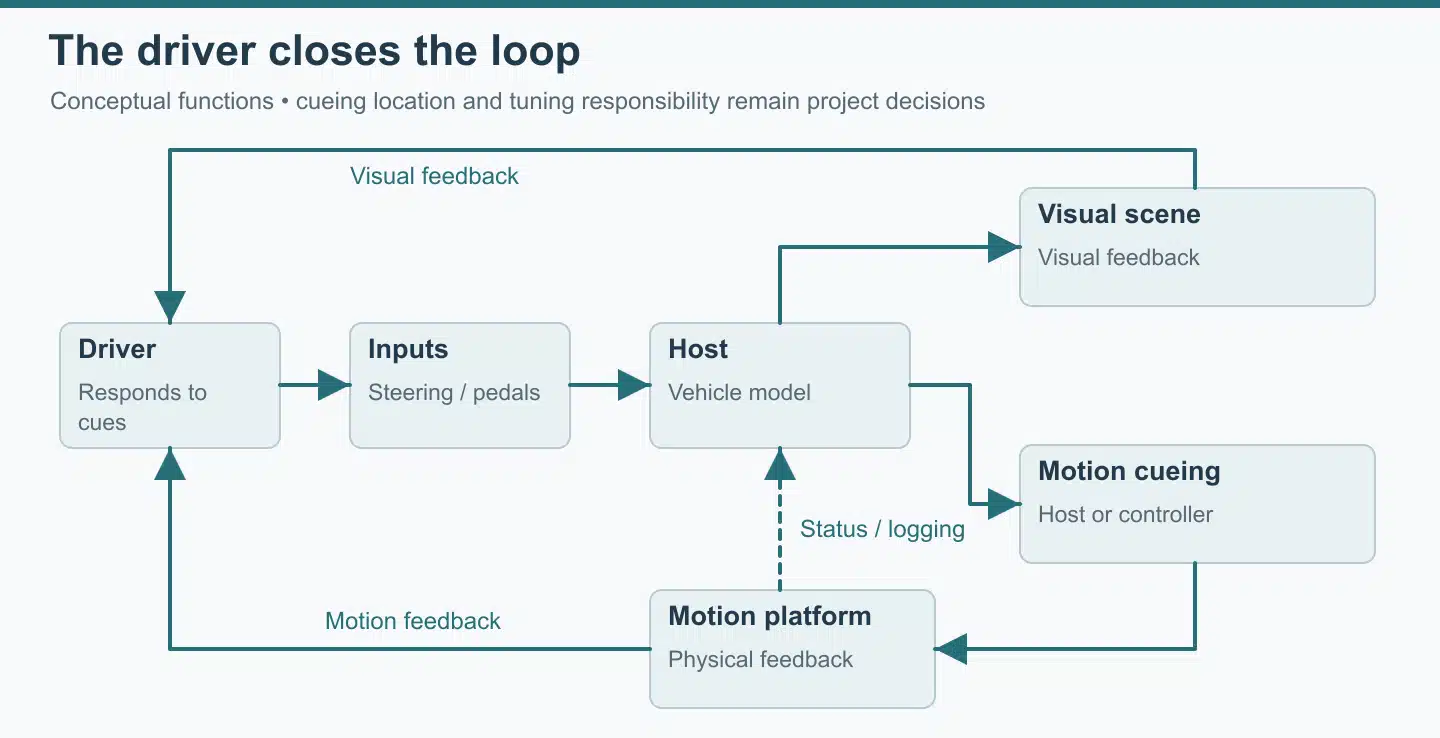
In vehicle development, describe which part of the driving experience the experiment addresses. A car steering system, a driver assistance function and a change in vehicle stability pose different questions. Driver feedback about steering feel may need to be considered alongside observed behavior; the lab should decide what evidence is appropriate before configuring the DIL setup.
Keep the physical prototype and the virtual environment clearly identified in the development process. A cockpit mock-up may represent only part of the eventual vehicle system. State which controls are physical, which behavior is supplied by modeling, and which environmental assumptions belong to the simulated road or scene. This helps reviewers understand the scope of the experiment without assuming that every element represents the final vehicle.
The sensory information available to a driver includes more than vision. If the study concerns perception of a maneuver, specify the feedback channels it relies on and who evaluates their combined effect.
A useful system drawing begins with driver inputs. Steering, pedals and other controls send information to the vehicle simulation. The vehicle model calculates a response under the selected road, traffic and test conditions. Outputs then feed the visual scene, control feedback and, where required, the motion-cueing process.
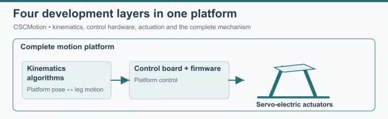
The motion-cueing process converts the relevant simulated behavior into a requested platform motion. Define the signal path between the host, cueing process and platform controller, together with the operating conditions specified for the platform. Visual and physical feedback reach the driver, who makes the next input. Platform status or reconstructed motion information may also return to the host for monitoring and recording.
This is a conceptual division of functions. A specific installation may combine some functions on one computer or distribute them across several systems. For each function, identify its owner, input definitions and process for controlling changes.
Agree early whether motion cueing runs on the host or in the platform controller, and who tunes it. Document the selected cueing location and tuning responsibilities alongside the host and platform interfaces. Assign an owner to implement and test each connection.
Use the interface document to connect the system drawing to actual signals. Record the meaning of each command, the units and reference it uses, the feedback returned, and the conditions under which motion is enabled. A field called “position” is insufficient if one team means an absolute pose and another means a displacement from a starting configuration.
The host communication options that can be discussed are TCP/UDP, serial, CAN and Modbus. The host and platform teams should select the method and define the messages together. Verify the selected connection with the intended simulation environment and required loop behavior. Review controller and API integration as part of the platform package.
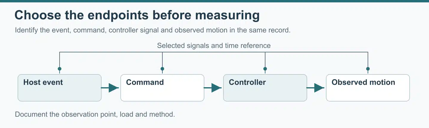
Also distinguish the commands sent from the information observed. A host command records a requested state. Controller feedback may describe an internal state or a pose reconstructed from actuator information. An independent measurement of motion at a point on the cockpit is another quantity. Label each trace with its source and measured or calculated quantity before comparing results.
When a cabin, seat or control assembly changes, update the load definition as well as the visual model. Added equipment may change the moving mass, center of gravity, inertia, cable routing or available clearance. Review the existing host command file against the new configuration after a mechanical change.
What the Motion Platform Must Deliver: Stroke, Dynamic Response and Timing
Start with the platform motion requested by the cueing process, together with the simulated vehicle trajectory that produces it. The supplier needs to evaluate what the physical platform is being asked to do. Supply representative sequences that include transitions and repeated operation, together with the moving load and the purpose of the test.
Evaluate the combined motion envelope
List the translations and rotations that must occur together. Separate axis limits do not establish the whole combined trajectory. Include the starting pose, the required path, the mounting arrangement and any movement of cables or hoses. Use the reference definitions in the platform interface document throughout the request.
Stroke is only one part of the review. The same cabin outline can produce different requirements when its mass distribution or mounting height changes. Include the cockpit structure, driver assumptions, controls and any equipment carried by the moving assembly. Label estimates and assign an owner to supply the final inputs.
Use the tool to size stroke and acceleration as an input-organizing aid, then submit the actual motion and load case for engineering review.
Define what dynamic response means for the test
Ask the team to describe the required movement over time. A pose sequence, a repeated maneuver and an oscillatory request may need different evaluation. State the amplitude, direction, loading condition, duration and repetition pattern relevant to the experiment. Avoid replacing those inputs with an unqualified request for high bandwidth.
If a bandwidth requirement is proposed, identify the input and output quantities and the method used to compare them. Specify controller feedback and physical motion at the driver’s location as separate quantities. The test team should specify the measurement locations, input and output quantities, and test conditions before comparing values.
The platform proposal should identify which requirements have been assessed and which depend on information still being supplied. That distinction is particularly useful when the vehicle model or cueing settings are evolving. A configuration evaluated against one request should remain traceable to that request as the host software changes.
Define the endpoints of a timing requirement
Timing language needs the same care. “Latency” can refer to several intervals, such as a host event to a command transmission, a command to controller processing, or a requested motion to an observed physical response. Choose the endpoints before asking for a result. Record the endpoints with every timing result.
For the complete simulator, assign someone to examine the relationship among visual, control and physical feedback. A platform supplier can address the portion assigned in the supply contract, while the system integrator must account for the connections and equipment outside that portion. Evaluate component behavior and the complete driver interaction loop at their respective acceptance stages.
Plan the records before testing. Identify the signals to capture, their time references, the configuration used and the person responsible for interpreting them. If an independent sensor is required, agree its mounting and reference. The test method and acceptance criteria belong in the project agreement, rather than being inferred from a communication protocol.
Include interruption and recovery in the interface discussion
Normal operation is only part of integration. Agree how the system should respond to a host interruption, an invalid command, a change of operating state or a request to stop. The surrounding simulator and the platform need compatible responsibilities for these situations. Record the required behavior in the relevant project documents before a human participant is involved.
The integrator must coordinate the complete installation, including access, restraints where applicable, operator controls and the site risk assessment. Platform-specific functions and limits should be confirmed in the supplied documentation and the integration scope defined by the project team.
Keep a usable record of an integration trial
Choose a representative driving scenario and document the version of every input that affects it. The vehicle model, cueing settings, cockpit configuration and platform command file should be identifiable from the same record. This makes the test repeatable enough for the participating teams to investigate a disagreement without guessing which setup was used.
Record the expected observation before running the trial. For example, the host team might need to establish that its commands are interpreted in the intended direction and reference, while the platform team checks the response specified in the test plan under the test load. These are distinct observations with different owners.
When an observed response differs from the request, preserve the relevant records and state where the difference was observed. It may be a host command, a reconstructed feedback signal or an independent physical measurement. Naming that location is more useful than assigning the issue to the platform or the model before the evidence has been compared.
Keep unresolved results visible at handoff. A missing signal, a provisional cabin load or an unreviewed interruption behavior is an open item, even if the rest of the demonstration proceeds. Assign a responsible person and specify the follow-up test. That gives purchasing and engineering the same view of what has been established and what remains to be completed.
Who Supplies What in a DIL Rig
Assign one owner to each interface and identify the records needed for handoff. A supplier may contribute to a task without owning its final acceptance. The proposed allocation below should be adapted to the actual contract, with open responsibilities resolved before integration begins.
Scroll horizontally to view all columns →
| Work package | Responsible party to appoint | Required handoff | CSCmotion scope |
|---|---|---|---|
| Vehicle and tire model | Customer or vehicle-model provider | Model version, inputs, outputs and intended validity range | Not included |
| Host and scheduling | Customer or system integrator | Command generation, timing definitions, logging and configuration control | Platform interface reviewed with the host team |
| Motion cueing | Project team to assign | Cueing location, tuning owner, requested platform trajectories and operating conditions | Agree whether cueing runs on the host or in the platform controller, and who tunes it |
| Motion platform and controller | CSCmotion under the project supply contract | Custom platform, controller and interface documentation | Supplied as the platform package |
| Cockpit, seat and driver controls | Customer or cockpit integrator | Mounting drawings, moving load, control signals and access requirements | Mechanical and motion inputs reviewed for platform feasibility |
| Visual scene and display system | Customer or visual-system provider | Scene configuration and coordination with the simulation | Not included |
| Complete system integration | Customer-appointed system integrator | Interface tests, combined operation and interruption/recovery review | Supports the platform integration tasks defined in the contract |
| Study design and validation | Customer’s research team | Test objective, participant procedure, reference comparison and conclusions | Not included |
Hardware integration also needs an owner for the steering torque and other control-feedback requirements when these are part of the experiment. That owner should coordinate the relevant controls with the vehicle model. Include the control-loading equipment and its integration in that owner’s work package.
Define the real-time system configuration and record where the motion-cueing algorithm runs and how it is versioned. Record tuning changes with the test results. Demonstrate real-time system operation under the trial conditions recorded in the test plan.
Use a single revision of this allocation in the purchasing and engineering discussions. Otherwise, the proposal may describe a platform while the laboratory expects a ready-to-run simulator. Naming the absent work is useful only if someone is assigned to provide it.
The interface handoff should include a contact for each side of the connection. Decide who reviews a message definition, who provides a host-side test, and who records the outcome. A successful exchange of data is an intermediate result; the system still needs to demonstrate the intended behavior under the conditions specified in the test plan.
Assign the mounting and site-service interfaces in the same responsibility list. The cockpit team supplies its drawings and load information. The platform review identifies the implications for the proposed configuration. The site team must confirm access, floor, power and space requirements using the project documents before installation is scheduled.
CSCmotion can provide sample FAT protocols and interface documents before an order. Use the samples to review the proposed evidence and responsibilities, then have the project teams approve the documents for their installation.
For the practical handoff, see motion platform integration. Keep the final supply list and the responsibility allocation together so that both describe the same project.
Choosing a Platform for a DIL Project
Begin with a short requirement package that the relevant teams can review together. Include the research objective, moving assembly, representative motion, available installation space, host arrangement and acceptance plan. Mark missing information with an owner and a date for resolution instead of filling the gaps with assumptions.
The motion requirement should distinguish essential test conditions from desirable future capability. That allows engineering to assess the current project while identifying where future changes would require a new review. An undefined future cabin or a different cueing strategy should remain an open requirement until its inputs are available.
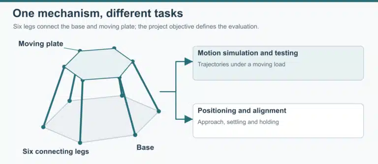
Compare degrees of freedom with the requested task. 3DOF motion platforms and 6DOF motion platforms provide different starting points for a project discussion. Ask which required motions can be assessed against the supplied load and trajectories.
All CSCmotion platforms are custom, designed around the customer’s load, stroke, speed and acceleration requirements. For the relevant application scope, review the driving simulator motion platform page, then send the inputs that define your installation.
Plan acceptance in distinct stages. First, agree the platform test conditions and records. Then define the host and platform integration checks. Finally, let the research team validate the complete simulator for the intended experiment. Keeping these stages explicit prevents a passed factory test from being treated as evidence of the whole study’s validity.
FAT can be witnessed on site or by remote video under the project agreement. Agree the load, trajectories, observations and records before the demonstration. If a representative host or cockpit is unavailable at that stage, document the substitute used and identify the checks that remain for system integration.
Configuration control continues after acceptance. Keep the approved motion inputs, interface version and software configuration with the test record. CSCmotion software can be upgraded or frozen at an agreed version. The system owner should decide when a change requires repeating relevant integration or experimental comparisons.
Before requesting a quotation, resolve the few gaps that block a meaningful review: what moves, how it must move, what sends the commands and who owns the surrounding system. Other details can be developed during engineering discussion, but these four questions establish the basis of the platform requirement.
Send your DIL requirements to CSCmotion for a free feasibility review and quotation. Include the moving-load information and representative motion, and identify the host team. The review addresses the platform package and the interfaces defined in the project documents.
FAQ
Does every DIL project need a motion platform?
The requirement depends on the driving task and the evidence the study needs. Define the research question before selecting the simulator configuration. A moving base should be evaluated for its contribution to that task, rather than added because the project carries a DIL label. The complete setup still needs validation for its intended use.
Does CSCmotion supply a complete DIL simulator?
CSCmotion supplies the motion platform, controller and interface documentation under the project supply contract. The customer or integrator is responsible for the vehicle model, host, cockpit, visual system and complete simulator integration. Agree whether motion cueing runs on the host or in the platform controller, and assign tuning responsibility before placing the platform order.
Which host communication methods can be discussed?
TCP/UDP, serial, CAN and Modbus can be discussed for the project. Confirm the selected method, message definitions and required behavior in the interface documentation. Verify host compatibility and complete-system timing under the test conditions specified by the project team.
Can we compare platforms using a latency figure alone?
Only after establishing that the measurement endpoints, signals, loading conditions and test method are comparable. Evaluate timing across the relevant parts of the driver’s feedback loop. Ask each responsible team to identify the portion it measures and the evidence that supports the result.
What should we send before requesting a platform proposal?
Send the intended study, moving-load and mounting information, required motion, installation constraints and host arrangement. Identify which inputs are final and which remain estimates. Include the proposed responsibility split and the acceptance questions that matter to the project so the engineering review addresses the actual integration.
References
- Human-in-the-loop driving simulation, for human participation and mixed simulation arrangements.
- Virtual commissioning with software and hardware in the loop, for the distinction between emulated control systems and actual control hardware.
- Using driving simulators to develop new vehicles, for the relationship between the research question and simulator configuration.
Discuss your project with CSCmotion. Share your application, moving load and required motion for a free feasibility review and quotation.